>>39790
Continued, for Grommet.
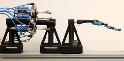
Mate, I was doing a bit of thinking - string tendons are a pretty appealing option, aren't they?
I mean, provided, the biggest disadvantage is hysteresis - the tendons may stretch, shift out of alignment over time (needing to be recalibrated), or tear - and repair might be a bit complex.
But, control is easy, motors can be housed quite a distance from the actual joint (permitting smaller joints), and, by using a non-compliant medium (metal cable versus pliable materials), we could keep stretching, tearing, and wear to a minimum.
Limit switches in larger joints might make recalibration easy - alternatively, manual recalibration, which would give a margin of error that allows for a few millimeters of stretch - that should last a few years, I would think. Direct-drive for larger joints, and cable-drive for smaller ones?
I've got a Chinese contact that can provide piles of cheaper servos - smaller components, and, it'd be easier to gear them, if we aren't as concerned with gearbox size - opens up quite a few options with using larger motors, too.
Correct me if I'm wrong, but, with single-automata scale millwork (belt & pulley systems), complex movements of single joints can be achieved with greater ease.
With a single tendon per finger, you could, fairly easily, contract all finger joints using a single servo.
Again, I don't know the first thing about robotics - so, if the idea is asinine, I do apologize.
But, I could reach out to my guys and see if they could source small pulleys, belts (high-rigidity, low-elongation / low-expansion), and servos.
I'll bring my own 3D printer to life, and try to make a prototype, if that'd be helpful.