OK, so when I was thinking of using both my discrete components motor controller design parts I already made and then also separately implementing the integrated half bridge IC design going forward, it hit me that the 8v- and arduino gnd tie together on the half bridge IC by necessity but this ruined their intended isolation I needed for my discrete components motor controller design particularly for the lowside switching portion of that schematic. On the lowside switching portion, the little mosfet has 12v- and arduino gnd tied to its source pin. If on the integrated half bridge I also have to tie arduino gnd and 8v-, then that means 12v- and 8v- and arduino gnd are all tied together always.
That completely ruined the necessary isolation between arduino gnd/12v- and 8v- that I had intended to be in place for my lowside switch setup. So that was bug #1 freshly introduced that I would then need to solve for in my discrete components motor controller design. When studying this out on the discrete components motor controller design, another error hit me: when any lowside switch turned on in the design, the 12v- dedicated power supply gnd and the 8v- motor supply gnd become connected as long as that lowside switch is on. Since every lowside switch had always access to 8v gnd on its source pin, then even one moment of 12v gnd and 8v gnd attachment anywhere on the robot would cause every lowside switch in the entire robot to immediately turn on at the same time. So if any turned on, then all turned on. This was a huge oversight. For some reason since I only designed and focused on one half bridge conceptually at a time, I did not consider the effects one half bridge has on its neighboring half bridges. This just never occurred to me. I guess conceptually I envisioned that every half bridge had its own personal 12v ground from its own personal 12v supply that was electrically isolated from the entire rest of the robot. But of course that's not practical even if it is technically possible. So in testing, things did work, but would have failed as soon as I tried to test more than one half bridge at a time. So I caught this bug before testing revealed it.
I discussed this horrible situation with chatgpt and it taught me that in a complex system like a robot, grounds of all your different supply rail voltages cannot be relied on to be isolated from one another like I was treating it. Even if at times they were momentarily, one switch, one change and suddenly they are not and it all becomes a common system ground again. So if I can't safely assume a ground for any given voltage is safely disconnected from the grounds of other voltages, I should not rely on switching on and off access to any particular ground to any of my lowside switches. Instead, I should be shorting the gate driver of the lowside switches to ground to shut them off rather than messing with their source pin's ground connections like I was before. I am to leave the source pin's ground connection as 12v- and its gate connection as 12v+ at all times except when I want to shut it off - at which point I short the gate pin to gnd using my logic level mosfet to do so.
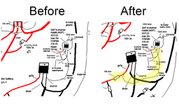
The fix was very straightforward and minor: I just had to add a 100ohm resistor in series with the gate pin of my big power mosfet lowside switch and then reroute my little mosfet a09t drain pin to the big lowside mosfet's gate pin instead of its source pin. The connection to its gate pin must be downstream of that 100 ohm series resistor so that the path from the big mosfet's gate pin has almost zero resistance when traveling through the little mosfet's drain line and over to its source line into ground. This way when you turn on the little mosfet, the big mosfet's internal capacitor quickly empties out, flushing into the path to ground created by the little mosfet and that discharges the big mosfet, shutting it off. When you want it back on, you shut the little mosfet off, which allows the big mosfet's internal capacitor to charge up again, which turns the big mosfet back on. So the setup now acts like a normally on relay.
Note: the resistor on the drain line of the little mosfet that we used to have when it fed into the source line previously is now removed. We want no resistance on there because that would impede the little mosfet's ability to discharge the big mosfet's internal capacitor in a timely manner. We want to be able to not only discharge that capacitor quickly but also direct all incoming current from the 12v+ line that makes it past the 100ohm resistor heading for that big mosfet's gate into our ground path. This rapid redirect flushes so much of that already limited current that hardly any can make it inside the gate of the big mosfet which causes the gate of the big mosfet's voltage to approach near zero volts. So it's called a "pull down" path to ground.
Attached is a photo of my schematic before and after the fix.
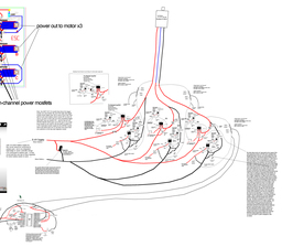
Attached is a photo of full updated schematic with the changes in place.
That all having been said, this discrete components original bldc motor controller design, now fixed, is worth keeping archived, but is now basically abandoned now that I have access to the time, money, and space saving shortcut of my integrated half bridge IC based design. It's kind of sad to abandon something I spent so much time on, but who knows, I may still use it if I ever come across a motor that I can't find a cheap half bridge integrated IC for in the future. It's a great schematic to have at the ready for that scenario.