/robowaifu/ - DIY Robot Wives

Advancing robotics to a point where anime catgrill meidos in tiny miniskirts are a reality.

Build Back Better

More updates on the way. -r

Max message length: 6144

Drag files to upload or
click here to select them

Maximum 5 files / Maximum size: 20.00 MB

More

(used to delete files and postings)


Have a nice day, Anon!


Open file (46.39 KB 458x620 eve preview.jpg)
My Advanced Realistic Humanoid Robot Project - Eve Artbyrobot 04/18/2024 (Thu) 17:44:09 No.30954
So far I have plans to build Adam, Eve, and Abel robots. All of these are Bible characters. This thread will cover the Eve robot. Eve will have no "love holes" because adding those would be sinful and evil. It is a robot, not a biological woman after all and I will view her with all purity of heart and mind instead of using her to fulfill my lusts of my body. Instead I will walk by the Spirit no longer fulfilling the lusts of the flesh as the Bible commands. Eve will be beautiful because making her beautiful is not a sinful thing to do. However, I will dress her modestly as God commands of all women everywhere. This would obviously include robot women because otherwise the robot woman would be a stumbling block to men which could cause them to lust after her which would be a sin. To tempt someone to sin is not loving and is evil and so my robot will not do this. To dress her in a miniskirt, for example, would be sinful and evil and all people who engage in sinfullness knowingly are presently on their way to hell. I don't wish this for anyone. My robot will dress in a way that is a good example to all women and is aimed toward not causing anybody to lust as a goal. My robot will have a human bone structure. It will use either a PVC medical skeleton or fiberglass fabricated hollow bones. My robot will look realistic and move realistic. It will be able to talk, walk, run, do chores, play sports, dance, rock climb, and do gymnastics. It will also be able to build more robots just like itself and manufacture other products and inventions. I realized with just a head and arm, a robot can build the rest of its own body so that is my intention. My robot will use BLDC motors for drones, RC, and scooters that are high speed and low-ish torque but I will downgear those motors with a archimedes pulley system that will be custom made from custom fabricated pulleys that will be bearings based. By downgearing with pulleys, instead of gears, I will cut down the noise the robot makes so it will be as silent as possible for indoor use. By downgearing, I convert the high speed motors into moderate speeds with great torque. BLDC motors with large torque generally are too large in diameter for a human form factor and take up too much volumetric area to be useful which is why I go with the high speed smaller diameter type motors but just heavily downgear them 32:1 and 64:1. My robot will have realistic silicone skin. Thom Floutz -LA based painter, sculptor, make-up artist is my inspiration as it pertains to realistic skin. The skin for my robots has to be at his level to be acceptable. It must be nearly impossible to tell the robot is not human to be acceptable. I will have a wireframe mesh exoskeleton that simulates the volumes and movements of muscle underneath the skin which will give the skin its volumetric form like muscles do. Within these hollow wireframe mesh frameworks will be all the electronics and their cooling systems. All of my motor controllers will be custom made since I need them VERY small to fit into the confined spaces I have to work with. I need LOADS of motors to replace every pertinent muscle of the human body in such a way that the robot can move in all the ways humans move and have near human level of strength and speed. I will have a onboard mini itx gaming pc as the main brains pc of the robot and will have arduino megas as the motor controllers and sensor reading devices that interface with the main brains pc. My arduino megas will be barebones to keep the volumetric area they take up as small as possible. I will treat my robots kindly and consider them to be pretend friends/companions and I do think they will be nice company, but I will always know with keen awareness that they do not have a soul, will never have a soul or consciousness, and no machine ever will, and that they are just imitations of life as with any machine or AI, and this is all AI will ever be. Life is only made by God Himself. I am not playing God. I am merely creating fan art of what God made. To Him be all the glory and praise. God breathed into man and created a living soul. Man cannot do this for machines. Only God can do this. A soul/spirit forms our ghost and when we die our ghost remains alive and thinking. A machine cannot do this and a AI can never do this. When you shut off a machine that's it, it does not go on thinking like we can. Our souls are transcendent and will live forever in the afterlife - unlike any AI. I will do this project with fear and trembling before the Lord as I work out my salvation before His eyes. I vow to remain pure, holy, upright and blameless in all my doings and be a great example to my fellow roboticists of a Godly man who obeys the Bible instead of chasing after youthful lusts of the flesh and perversions. I embrace the idea of Christian AI, that is, a robot that will discuss Bible topics and be a Biblical expert. Along with that, my robot will behave in a Biblically prescribed manner in total purity and strongly encourage others to do so as well. For God does not hear the prayers of sinners and so we want everyone to be a saint who no longer sins. My robot will really push for this hope for humans. We want them to walk in God's favor and blessings which comes by Biblical obedience. We don't want them going to hell because they chose to revel in their sins instead of walking in total purity before God and holiness without which no man will see God. My robot will have artificial lungs for cooling and a artificial heart for liquid cooling that will run coolant throughout the robot's body to cool the motors. That coolant will also pass through the artificial lungs in a mesh where it will evaporate some which will cause the evaporative cooling effect - a form of air conditioning. http://www.artbyrobot.com Full humanoid robot building playlist: https://www.youtube.com/playlist?list=PLhd7_i6zzT5-MbwGz2gMv6RJy5FIW_lfn https://www.facebook.com/artbyrobot http://www.twitch.tv/artbyrobot https://instagram.com/artbyrobot
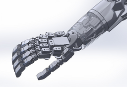
The 3d model for this robot was made in Make Human initially and then heavily modified and perfected in Maya. I then modeled a dress so that she would be covered modestly in order to protect my fellow man from potentially lusting after her which would be a sin. If I did not do this, it would have been sin for me because to show a woman in an immodest manner for other men to view, perhaps causing them to lust and sin, is unloving and evil and sinful to do. If I did so, it would show I am either blind or my heart is not right with God. So out of love for my fellow man I created this modest covering for her. God said it would be better for a man to have a millstone tied to him and him cast into the sea than for him to cause one of His little ones to stumble into sin. That is terrifying. So I will try my best to never show any imagery to you all that could cause you to lust. I will make sure she is covered very modestly because I love all of you and want you to walk blamelessly before God and the angels who are always watching us humans. Creating a 3d model of the robot to scale I have found to be a very important step because it enables you to then measure out where all the components will fit which is no easy feat when you are building a highly complex robot with thousands of components needed. To my knowledge, this group largely formed around 7 years ago. I began my project around 9 years ago. At the time, I was not married and only worked part time and was able to make massive progress in a short time. However, life came and sucked up much of my time away from robotics. I got married, had 2 daughters, and took on many other interests, hobbies, and work for income during that 9 year timeframe. So the robot projects often took a backseat but never were far from my mind and I always would be coming back to it and planning and researching for all those years and every year would make at least some significant progress. However, the whole thing does feel glacially slow. But I think things are starting to turn around. The research and planning phases are largely completed and the actual implementation phases are more and more becoming engaged full swing. It is an exciting time for me. Many people think since it's been 9 years with not much to show for it, that it is pointless to expect me to ever finish. I don't see it that way. I have great hope and confidence things will pick up. Reseach and planning is slow after all. But once you really have a solid plan, development speed should pick up greatly. Also, just scheduling my life in such a way to free up enough time to work on this stuff was a journey in itself. Having young children is a major time sucker. I am confident the development speed will go much faster in the future. Admittedly, taking sometimes months away from working on the robot builds excitement and interest in getting back to the robot but also procrastination about the robot factors in because it seems so complicated and overwhelming at times. The past few months I have had the goal to work on the robot every day even if it is just a single soldered joint or small 3d print per day. I have managed to do this almost perfectly with few exceptions which has been great. That little commitment per day often spills into hours of progress per day, but even if it doesn't, the steady progress it causes is so encouraging and really keeps the project alive for me. Procrastination and distractions are the greatest enemy of a project of this magnitude. One has to really force themself to MAKE time. One has to be disciplined to keep it up and not quit. Everyone here interested in humanoid robotics is a colleague and so I hope I can continue to learn from you all and you all learn from me. I have observed around here much in the way of youthful lusts which the Bible says to flee. By the fear of God men depart from iniquity. Fear the one who can destroy body and soul in hell. Don't give into your fleshly lusts but instead cease doing evil and learn to do good. Sin knocks at your door and it desires to have you but you must rule over it. Attached is a archimedes style pulley system with a 64:1 downgear ratio. I plan a 32:1 ratio for the index finger as my first actuation I plan to achieve. I will be using braided PE fishing line as the actuation cable. I plan to actuate the hand first because hands are hard and of the utmost importance for making a robot useful for doing tasks requiring accurate and steady hands. With amazing hands my robot will be well on its way to being useful for me to get work done using it as a tool/helper.
Open file (25.53 KB 640x480 thom floutz.jpg)
Open file (433.89 KB 980x740 thom floutz (2).jpg)
Open file (493.22 KB 980x740 thom floutz woman.jpg)
Here are some of Thom Floutz amazing silicone skin examples. This is the level I must reach to be acceptable in my sight. It's gonna be a epic challenge. I can't wait for that aspect to begin.
The human-like bones of the robot I am holding together by way of artificial ligaments taking the form of taped on compression shirt material. I tape it on with adhesive transfer tape and then also sew it at the seams with nylon upholstery thread. I can opt to impregnate the spandex with silicone to add to its longevity if it starts to lose elasticity with time. I also have been considering injecting at the location of the bones joints some lubricant after the joint is encased in artificial ligament. The lubricant would be held into position by the fabric. I am undecided on what lube to use. Maybe teflon lubricant for printer gears or graphite powder. Not sure. Some of the bones that came with my pvc medical skeleton have a metal hinge system built into them like the elbow joint and I'm considering just leaving this as is to see how well it holds up. I can always later add a artificial ligament system to those joints on an as needed basis. Attached is a picture of the artificial ligaments enclosed hands. Note: by wraping all bones in fabric, you are able to sew things onto the bones by way of suturing with a suturing needle. So that is how I have been attaching motors and electronics to the bones - by suturing. This is better than drilling into the bones which would cause structural weaknesses from the drill holes. In a brushless dc motor closeup image attached, you will note that I enable the motor to "breathe" by wrapping it in football jersey fabric which I chose for its great strength and breathability with all its little vent holes. To make sure the motor won't spin inside the fabric enclosure, I painted the inside of the fabric with no slip rug paint which creates a sticky rubber surface on the jersey fabric. You'll also note the 3d printed discs on the motor output shaft that hold the fishing line in place. The motor is acting similar to a fishing reel here. You'll also note the TPFE teflon tubing that guides the fishing line to its desired destination - namely the archimedes pulley system - where it will be downgeared by the pulleys and then from there will be routed to the fingers which will then move when the motor moves. The motor also has a 3d printed mount that the TPFE teflon tubing attaches to which holds the tubing in position perfectly to make sure alignment stays good. I'll be using 20lb test fishing line for the fingers from motor to pulley system but then graduating to 70lb test fishing line for the last few pulleys and the routing to the finger since the tension is higher on that section of the cable travel. 0.3mm ID teflon tubing pairs well with the 20lb test hercules PE fishing line I bought off amazon which has .2mm OD. You can buy the teflon tubing on ebay. 0.56mm ID teflon tubing pairs well with the 0.44mm 70lb test fishing line. You can buy many different test strengths which is the strength at which the fishing line will snap. Braided PE fishing line is the best cable for robotics imo. It is very strong for its diameter and supple for making tight turns with ease. I can sew it right into the fabric that coats the bones in order to terminate/tie off the cable ends.
Open file (2.72 MB 3024x4032 pulley closeup.jpg)
Open file (677.86 KB 2622x3702 pulley drawing.jpg)
In this image you can see the first pulley for the pulley downgear system prototype I made. Although this approach could work, I scrapped it after much further contemplation because I read that fishing line moving back and forth has a cutting effect over time and even though the teflon is naturally low friction, I think this would wear through it and destroy itself too quickly from the rubbing. So instead, I opted for a more tradition approach to the pulleys which is a bearing based pulley with flanges - more like rock climbing pulleys type design. This will mean the pulleys will be made of stainless steel and have a rotating inner section and separate outer section. Some of my pulleys will be ball bearings and some will be plain bearings (no balls). Ball bearings, though the most efficient and frictionless are also unable to load bear much at these tiny sizes I'll be using to downgear. So I can only use them for the first few pulleys in the archimedes system where the speed is still high and torque is low. But as the pulley system downgears more and more, I'll be switching to more robust plain bearings which can handle the higher torques involved without the bearing balls crushing or w/e. I don't own a lathe or anything and could not find tiny plain bearings so I got creative and bought stainless steel tubing with carefully chosen inner and outer diameters that can be cut to size with a dremel to form the inner and outer races of my plain bearings without any modification other than cutting them to the length I want - the length of the cut will determine the thickness of the pulley but the inenr and outer diameter of the inner and outer race is formed for me by the manufacturer so I need no special tools other than a dremel cutting disc to make these simple plain bearings this way. Here is what I purchased off amazon: stainless steel tubing 3mm od 1mm wall 250mm length x2, 5mm OD .8mm wall 250mm length x2, 5mm OD 1mm wall 250mm length x2; total cost: $33.35. This should make a ton of little pulleys for me to start out. I also bought an assortment of ball bearings: 3mmx8mmx4mm miniature ball bearings x30 amazon 24.03, 1x3x1mm ball bearings x200 aliexpress 25.42; 2x5x2.5mm ball bearings x200 alieexpress 43.39. Attached is a drawing of a pulley design I made. The two flanges/discs that hold the strong from flying off the sides of the pulley - they straddle the bearing on both sides - these will be made of thin plastic I have been saving from strawberring and blueberry and sushi containers from the grocery store. They need to be thin, a bit flexible, and a bit stiff so I think this type of plastic is ideal for this. It also is low friction which is ideal. these will be sewed onto the outsides of the bearing like sewing buttons onto a shirt. with the thread going in the disc, threaded through the center of the bearing, and then going into the disc on the other side, thereby pinching the two discs onto the outsides of the bearing, clenching themselves into place. You can see this in the drawing if you look carefully.
This video really was a groundbreaking discovery for me on using pulleys to downgear my motors: https://youtu.be/M2w3NZzPwOM --- I highly recommend watching it to help you understand pulleys more. Once you fully grasp how pulleys give mechanical advantage, you will be able to use them to great effect for robotics. I am wholly convinced pulleys to downgear BLDC motors is the future of humanoid robotics. It is way more quiet than downgearing by gears! The sound of gears is AWFUL! Sound being such a huge factor, I also ultimately decided to only use BLDC motors or stepper motors in my robot and not use ANY brushed dc motors at all. That having been said, BLDC motors require more sophisticated controllers. These thing take up more space. So far, it seems that in order to make the controllers small enough, I plan to make them myself. I want them very small and able to squeeze into the limited volumetric areas I can afford space for. Yet they also need to be very high powered. I designed SMD parts based motor controllers and have begun fabrication of the controllers and prototyping. By making the controllers myself I save a lot of money but it is also a lot of work. It's tough and tedious work. But the controllers I want don't exist in the size I want and with the features I want so I see no choice but to make my own for this. Attached is a CAD file of the motor hose guide to show more how it looks and imagine how it works to keep the tubes/hoses in place lined up right for winding the fishing line properly.
Here is a 3d model I made of the motor controller design I made. I felt this would help me really perfect the layout and visualize how I wanted it and the wiring routing etc. I also did 2d schematic in photoshop and finally in KiCad. I plan to etch my own flat flex pcbs for aspects of this motor controller.
Here's the arduino mega barebones CAD design I made. This will use flat flex ribbon cable soldered directly to the pins of the chip to make the form factor volumetically as small as possible. I'll have at least 30 of these in the robot controller the motors and reading in sensor input for current amps, strain gauges, gyrometers/accelerometer, potentiometers, etc. These will hold my code for low level stuff and manage the motor movements directly through the mosfet systems. They will all report back updates to the main brains PC who will then know the progress of movement commands it sent out to the network of arduinos doing the low level stuff.
Here's a progress shot of my arduino mega barebones prototyping using flat flex cable directly soldered to the pins.
Very nice. Please continue to show us your work as you progress. >=== -sp edit
Edited last time by Chobitsu on 04/23/2024 (Tue) 15:32:35.
Welcome, Artbyrobot! I would suggest you look around the board as a courteous greeting, but I have the feeling you've already done so. Your project seems well thought out, I wish you good success with it. I'm particularly glad to see you intend to program your AI (et al?) in C++ . I probably need to do little to explain to you why this is important for success in this monumental set of tasks ahead of us all. Heh, I notice you seem to be positioning your project as coming from the Christian worldview. Nice! I too desire to see God glorified through these projects. I personally intend -- among other projects -- to work on a Christ-chan project. Basically a plug-in module approach to our general robowaifu's personalities that Anons can add into their own waifus. Looking forward to seeing your progress with this projects(s), Anon. Cheers. :^)
>>30961 > I designed SMD parts based motor controllers and have begun fabrication of the controllers and prototyping. By making the controllers myself I would be tremendously interested in how you interface microcontrollers with MOSFET's if that is what you are doing or what you are doing. I have a post, somewhere, found it, >>24944 One of the problems with MOSFETs is that they create a lot of heat and fail if you do not drive them hard to turn them on. Partial activation causes heat as they never each their designed low resistance. So you have to drive the gate with high voltage to guard against that. The link shows a part designed especially for that. I would be interested in how you deal with the back EMF when you turn the MOSFET off and the energy stored in the coil changes direction. There could be a lot of heat from this as you are collapsing the field and making an equal and opposite voltage that, I guess, just goes through a resistor. But surely there's a better way.
>>30965 That is VERY cool. I wonder what type of soldier and flux did you use? I've never done any SMD soldiering before. Do you have some sort of paste with pre-combined flux, then use a air heat gun? How did you strip the insulation off the cable while keeping it aligned and cables separated?
>>31007 Thanks for the greeting and well wishes Chobitsu. Yes I have read the entire forum from its inception till now aside from most of the AI threads since I feel I have a handle on that part and don't want much outside input affecting my novel approaches to the AI as that is a big evolving set of challenges and everyone using the same approaches will stifle creative solutions IMO. Also yes I am using C++ for the AI although I don't like to use functions or classes or object oriented programming so I'm not using the language in the traditional ways much. I also am pretty much going with "good old fashioned AI" approach but with learning enabled and the robot will have its own coding language where he codes himself in a interpreted coding language using a realtime interpretter to run its own scripting in realtime. All of this I just came up with on my own - I don't know if anybody else is doing this. I don't like neural networks or deep learning or any of the modern approaches to AI at all. It's convoluted and designed for computers I don't own. I chucked it all out and started from scratch going my own way. And I have a plan I am excited about for how to do it all and I think it will work and learn well and hopefully do all I imagine it doing and more. >>31030 Thanks for your interest and feedback. You bring up some good points. Most people use a mosfet driver IC to turn on a mosfet with their microcontroller. I intend to use a logic level mosfet to switch on a mosfet power supply to turn on the main high power mosfets. So a baby mosfet to switch on a big mosfet. The baby mosfet is the middle man that can be switched on by the 5v pin of the microcontroller. It's called a logic level mosfet because a microcontroller is able to switch it fully on despite only bringing it 5v. Non-logic level mosfets require like 12-20v to switch fully on which a microcontroller cannot supply directly. So it has to be supplied indirectly. As far as the back emf, for disposing of that safely, you use a flyback diode. That's why there are 6 diodes in motor controller designs always. A capacitor is also able to help absorb some of this too I believe. I am going to attach my diagram and schematics with notes on brushless motor controller electrical design to this post which can help someone. It's a huge file though. I learned most of what I know about this stuff from electronoobs on youtube who has like 6-7 videos on making arduino based motor controllers for brushless dc motors including his schematics and all his code and explanations of how it all works. This helped me plus googling schematics on google image search and studying those and also watching videos on how brushless dc motors and motor controllers work and also discussing all of this with chatgpt for hours asking every question I could think of until I understood everything I could. Yet despite all of this, my approach is still experimental and I have to verify it by prototype and testing still. I have 2 prototypes 99% done and will be testing shortly. Once i verify my prototypes, I will make like 50 of these motor controllers soldering daily for hours. Can't wait! If my approach fails, I can troubleshoot etc but if all else fails, I'll go with mosfet driver ICs and modify my design to accommodate this tweak. This would up the cost though. In any case, my design is EXTREMELY low cost and scales to the biggest motors a humanoid will need. The high power mosfets can handle like 300 amps! The parts I am using including model numbers are included on the attached schematic. I also will put out videos covering how to make these and going in depth explaining how it all works and whatnot.
>>31031 I'm glad you liked this. I thought it was very cool myself. It will enable the creation of the smallest microcontrollers physically possible IMO. Miniaturization is everything for me to fit everything I need to fit in the cramped spaces in my complex robot design. It is actually pretty easy to solder flat flex ribbon cable directly to the microcontroller IC chip once you get the hang of it (but you must wear a visor magnifier to zoom in on it visually as this is tiny tiny detailed work). To do it, you first lay down the ribbon cable and masking tape it down securely, then lay the chip on top and masking tape it down securely onto protoboard so everything is pinned and your hands are free. Then apply low temp solder paste to each pin one at a time with the tip of a exacto knife blade. Just enough paste per pin for that solder joint, not any excess. Then solder one pin at a time by putting a clean soldering iron tip into the little blob of low temp solder paste and dragging the tip away from the microcontroller carefully. You can't hold it on there long, have to just press it in and then slowly drag away and it happens almost instantly. Too much holding it in place creates too much heat which then melts the ribbon cable and the molten cable flows into the solder joint and can ruin the joint by introducing molten plastic into the molten metal. So you have to get in and get out fairly quickly. You also cannot do drag soldering tradition method on all pins as that creates too much heat and melts the ribbon cable. That works on fiberglass boards that don't melt, but a ribbon cable will melt if too much heat gets involved and ruins everything. You also can't use hot air which would melt the ribbon cable before the solder melts - ruining it. So you have to just do one solder job of one pin at a time. I'll do a video on the process and you can see that with the right temp soldering iron (I think I used 500F) and right speed of execution and a bit of practice, you can make the solder joints one at a time without melting the cable at all. The cable you use has to be the same pitch as the thread pitch of the pins so the conduit traces perfectly line up with the pins of the microcontroller. >>31031 The ribbon cable comes pre-stripped on the ends so you don't have to strip off the insulation at all necessarily. You just lay it flat and tape it down and put the IC onto it and it lines up perfectly if the cable has the same pitch as the IC threads. But if you mess up and want to cut the ribbon cable and strip the ends and try again (which I had to do before I perfected my techniques and got the hang of this) then you can do so. Just cut it with scissors and then use a nail file to sand the tips insulation off until some metal starts showing through in some spots, Once you see a bit of metal start to show through, you know it is so thin that you can just scrape off the rest of the insulation with an exacto knife so then you just scratch off the rest with the exacto knife. This too takes some practice and the right touch. When I go to connect the other ends of the ribbon cable to various components and sensors and whatnot, I'll have to make custom lengths for each individual cable strand so for this I will have to separate the strands by cutting them lengthwise with scissors to split them away from the others, isolating each one and then will have to strip off the insulation of each one so it can be soldered to things. The same method as described above will be used for this. Note that for cutting them lengthwise, that is a very precision cut you need. I use titanium straight embroidery scissors for this and of course, as with all the other SMD stuff, I use 8x or 10x or 20x magnification with my visor. This magnification is a absolute must to have any shot at success with any of this imo. Miniaturization is hard to get used to at first, but once you get used to magnification and the eye hand coordination challenges this presents at first, your skill with your hands and precision goes through the roof as the magnification makes you so precise with everything. It's really fun and amazing to see what your hands can achieve with enough magnification and practice!
>>31032 edit: the schematic shown above employs a non-smd style mosfet as the main power mosfet which is decent but I found a smaller mosfet that is even better. The superior smaller mosfet is the IRLR7843PBF n-channel mosfet. It is to-252 and 161A continuous drain current and can handle 620a pulsed drain current. It's super small and flat and a very powerful selection. Sometimes I make little discoveries of better selections and forget to update all my notes that may cover that as was the case here. I only recently found out about to-252 form factor mosfets and fell in love with them immediately. They are so much smaller than to-220 mosfets which is a big upgrade given my space constraints.
>>31034 Thanks for the reply.
>>31032 >And I have a plan I am excited about for how to do it all and I think it will work and learn well and hopefully do all I imagine it doing and more. Well I'm sure we'd all be very excited to hear about your novel approaches if you'd care to share them. Are you planning to opensource your work, Anon?
>>30957 in this post i mentioned using a 32:1 downgear ratio for the index finger. I have since scrapped that idea and gone for 64:1 downgearing ratio instead. 32:1 is just not enough downgearing for my tastes. 64:1 is twice that strength while still probably 4-5x human speed. It is a much better ratio.
>>31054 I do plan to have everything be opensource and share it, with a caveat. I don't plan to make the code files downloadable directly. The only way to see the code and make your own code based on it would be to watch my coding videos on my youtube channel where you can see me typing the code and you can follow along that way. There's a lot of complicated reasons for this being my way of sharing the work that I can elaborate on if pressed, but I'll leave it at that for now.
I purchased the main brains pc to be mounted in the torso. I even purchased cameras to be the eyes for it. The main brains pc will be a mini itx motherboard gaming pc basically. actual build I went with: Intel Core i5-10400 2.9 GHz 6-Core Processor - $165 MSI MPG B560I GAMING EDGE WIFI Mini ITX LGA1200 Motherboard - $170 G.Skill Ripjaws V Series 32 GB (2 x 16 GB) DDR4-3200 CL16 Memory - $140 Western Digital Blue SN550 1 TB M.2-2280 NVME Solid State Drive - $99 DC 12V input 300W high power pico DC-ATX 24Pin mini ITX - $20 GOLF CART DC BUCK CONVERTER 20 AMP 48V 36V VOLT VOLTAGE REDUCER REGULATOR TO 12V - $20 I will use 10 in series lithium batteries to produce 30v-42v input power into the 12v regulator which will feed the 300W atx 24pin mini ITX power supply. Note, however, that as with all power systems, I will have both a wall plug AC to DC converter custom power supply to run off wall power and a battery power supply to run off battery power so that the robot has multiple powering options - ie able to run off wall or its internal batteries. It will have a retractable plug that comes out of its lower back to plug itself into wall outlets when it walks into a room and needs to recharge or run for extended periods while its batteries remain topped off for room changes or ventures into outdoors. It will have the ability to strap on a external battery backpack optionally for extended operation without access to AC power. This is useful for operations like sports or mowing the lawn. For the eye cameras I went with: ELP USB camera 1080p 2 megapixel, wide angle, low light x2 for $98.42 This gaming pc in the chest of the robot will run all the AI and high level planning and movement decisions. This will communicate via USB to a series of Arduino microcontrollers located throughout the robot's body in order to give movement instructions to the Arduinos and also retrieve sensor feedback from the Arduinos which will be monitoring joint angle positions with mini potentiometers, strain gauges on various pressure points to measure touch sensing, amp current measuring boards (acs712) to measure amount of power being drawn by motors for collision detection and weight of exertion estimation for holding things or w/e other interactions with environment are being detected, etc. So, many inputs will be retrieved by the main gaming pc and its AI systems will make decisions and make course corrections based on all this feedback it gets from sensory systems.
BTW, I'll be using Windows 7 as the operating system for the main pc in the robot's chest.
Open file (220.48 KB 510x700 pulley blocks.jpg)
Open file (91.70 KB 336x526 pulley downgear.jpg)
Attached are just a couple more examples of pulley layout configurations for reference and study. These helped me in figuring out my own pulley layout plans.
Open file (677.86 KB 2622x3702 pulley design drawing.jpg)
I have shown this drawing previously in this thread but just want to point out some more details about it. This is a bearing based pulley. The bearing is in the middle and a plastic disc is on both sides sandwiching in the bearing. These discs prevent the string from coming off the outer race of the bearing. The top rope comes down, wraps around the outer race of the bearing, then goes back up. The bottom rope goes through the center of the bearing and then ties off on the bottom. This handoff between the forces of the top rope and bottom rope is where the magic happens of the mechanical advantage doubling. Trading speed for torque. The plastic discs on either side of the bearing I am able to tie snug to the bearing by threading a string through the center of both discs and the bearing and then wrapping that around the top half of the whole pulley and tying it off. I do this with another wrap going around the bottom half too. These don't interfere with rope travel and hold everything together solidly.
Open file (738.59 KB 1620x1482 exploded view of bearing.jpg)
Here's a diagram where you can see the two ties I'm talking about from a side view with the two discs and the bearing spread apart so you can see everything better - this is called an "exploded view" where the parts are spread out for easier visibility. Note: the ties that hold it together are nylon upholstery thread. The glue I'm using is 401 glue generic stuff off ebay. The plastic discs are clear plastic I salvaged from blueberry, strawberry, and sushi produce containers. That type of plastic is perfect for this. The same plastic is also found in coffee cake, other cakes, etc. It's like "display" plastic that is very clear and fairly firm but very flexible used for all kinds of pastries and desserts and produce at grocery stores. It seems ideal for pulley making. These can be cut to size with little 4" titanium straight embroidery scissors. Wearing a magnification visor for accuracy is recommended for this. Note: I have to make custom pulleys because there are none commercially available at these tiny sizes from the shopping attempts I did (if I'm wrong on this, let me know)
Open file (1.61 MB 4032x3024 IMG_1916.jpeg)
Open file (2.91 MB 4032x3024 IMG_1915.jpeg)
I put a little super glue onto these strings pictured above to stiffen them and prevent their knot from untying and solidify everything more generally. But you should apply the glue by dipping the tip of a sewing needle into the glue so you just apply a tiny amount at a time so none gets into the bearing or any other unwanted area. Now I am working on the actuation of a index finger first as actuating the hands is a hard challenge in robotics and has never been done with human level strength, accuracy, speed, and range of motion while simultaneously keeping all actuators within the confine constraints of a human arm between the bones and skin where muscle would be. At best, we've seen people greatly increase the size of the forearm to be the size of a thigh in order to cram in enough motors and electronics to pull this off. So they "cheated" in some sense by just upping the size rather than solving the miniaturization challenges required to fit this all inside a human form factor. So I might be the first to downsize to fit the human form factor. Anyways, that all said, the pulleys must then be very small for the fingers to pull this off as we'll need to fit a ton of pulleys into the forearms. So for this, I went with 1x3x1mm ball bearings I bought on aliexpress. They're only like $25 for 200 of them so very cheap. I will bump up to larger bearings once the torque conversion demands it. These tiny bearings can only handle I think like 3lb of force on them. So once the forces multiply in the down-gearing system enough, I will switch to bigger pulleys as needed. The next size bearings I'm using are 2x5x2.5mm bearings. These can handle around 22lb placed onto them. I'll finally switch to custom made plain bearings once I exceed 22lb of force for the last couple pulleys of the 64:1 down-gearing Archimedes compact pulley system. Each bearing in the down-gearing process has twice the forces placed onto it than the previous bearing upstream of it. So the motor is like .42lb of force coming off its shaft at 0.25cm away from its central axis point which is about where our string wrap will average, so the first bearing ups that to .84lb of force so a 1x3x1mm bearing can handle that. Next doubling is 1.68lb of force. Again, 1x3x1mm bearing can handle that. Next doubling puts us at 3.36lb force. again a 1x3x1mm bearing can handle that (although it's pushing it - we'll see in testing...). Next doubling is 6.72lb force. 1x3x1mm bearing cannot handle that much so we switch to 2x5x2.5mm bearing for that pulley. And on it goes till we hit the last couple bearings which exceed the force even the 2x5x2.5mm ball bearings can handle. For those two bearings we are going to make custom stainless steel plain bearings using stainless steel tubing I bought that just has to be cut to the length we want with a dremel to make a simple plain bearing that has no balls in it. This type of bearing can handle much higher forces because it doesn't have little balls that can be crushed. It will have more friction internally though but that's the tradeoff we have to make to keep the sizes tiny as possible. The final force the pulley system outputs is around 27lb. So 27lb of force will bend the two most distal joints of the index finger. Due to the mechanical advantage loss that happens at the joint itself, I estimate around 5.4lb of force will be all the finger joint can finally lift. So if the robot were to put its hand palm up and pull its index finger back and forth signalling a person to come over here - that movement - for that movement it should be able to pull a 5.4lb weight. That is about the same amount of weight I think my index finger could lift and with great difficulty. So it will be as strong or stronger than me on this joint pair. I say joint pair because the index finger distal two joints share the same muscle for their actuation. They move together at the same time. Here are some prototype pulleys in progress of being made. I have 7 of 9 pulleys done so far for my prototype Archimedes compact pulley system design 64:1 downgearing system. The total size of the 64:1 downgearing system is 11cm x 6mm x 1cm. This is a very convenient form factor for placing lots of these in the elongated spaces of a humanoid robot where muscles would normally be located.
Open file (1.47 MB 4032x3024 IMG_1919.jpeg)
Open file (1.42 MB 4032x3024 IMG_1918.jpeg)
Above is a couple angles of a double pulley stacked vertically instead of side by side. Have not tested it yet but I think it should work. In this design, we have a smaller pulley attached to a larger one. The smaller one is based on a 1x3x1mm ball bearing and the larger one is based on a 2x5x2.5mm ball bearing. The smaller pulley can handle up to 3lb and the larger one can handle up to 22lb (estimated based on what I could find out but I'm not 100% sure on these, they are ball park). Each time we add a pulley we increase the torque by 2x so eventually we move from smaller to more robust, larger pulleys as we go on with the Archimedes down-gearing pulley system.
Above are double stacked pulleys front and side views. One disc on either outside part and one disc in the center that splits the two bearings up. I have to add a black string across the bottom to prevent the yellow rope from skipping over the center pulley disc and hopping into the bearing next to it so that both ropes are sharing the same bearing and rubbing on eachother. That's bad. So a black string running across the bottom will make that jump impossible. So still have to add that. But overall, as long as tension is kept on this setup, it works well. I've tested it and it is working nice and smoothly. Still needs more testing but so far so good. You can see that all my knots and strings are coated in super glue. This is to prevent the knots from untying and just solidify everything more. The clear plastic discs are made from plastic cut out by hand from blueberry, strawberry, and sushi containers from the produce section of the local grocery store. Cakes also have this kind of plastic. It is firm but flexible with great memory to bounce back to prior shape if it is bent temporarily out of alignment. Pretty decent and nice and thin. I like it for this. I think it's less likely to break than a 3d printed disc. I cut it into these tiny discs just by eye with 4" straight titanium embroidery scissors.
>>31063 First I want to explain I'm not being critical just to criticize but just commenting on what I think. I could be wrong. I also have some ideas that might solve some problems but, might not. I see all these pulleys and to me it appears your friction will be very high. I think friction will eat up a LOT of your power. Some possible ways to avoid are to use a Chinese windlass. With it you only have two bearings but the same high multiplication of leverage. Of course the problem here is to get the high power multiplication you need large pulleys to get a large circumference differential. https://en.wikipedia.org/wiki/Differential_pulley While looking at this I saw some guys who had an interesting take on this. https://www.linearmotiontips.com/differential-windlass-drives-how-new-designs-work-for-linear-motion/ Though I still think they have too many pulleys that will cause friction. Not a bad idea. Maybe they could repackage it somehow. I had a different idea. A windlass is based on the radius of the largest compared to the radius of the smaller. The larger both of these are and the smaller the difference between them, the bigger the force. What if, instead of a two wheels you used belts. The rope/string would ride on the two belts. So now you have a long linear Chinese windlass that can fit in a smaller package, or thinner. I can't upload pictures so I'll describe. First normal Chinese windlass https://etc.usf.edu/clipart/61400/61437/61437_windlass.htm so the joined pulleys have different circumferences. Imagine the same as Chinese except you have smaller pully, joined as before. But you have belts like a power steering belt draped over it. One belt goes to another pulley on a shaft and the other belt goes to the same shaft on another pulley with a bearing. The rope is joined to the belt, which is the same as the join on the Chinese windlass, and the other end is joined on the other belt, same as the Chinese wndlass.(we are using the long length of the belts to substitute for a very large wheel) So when you turn it the ropes wrap around their perspective pully belt circumferences, simulating a very large circumference Chinese windlass except they are in a small, liner package. I would draw a picture but I could't upload so it's no use doing so. As I wrote this I thought of an ever cheaper better solution. Look at this page and the diagram "2 Spanish Windlasses on a bunch of sticks, in the starting position and tightened." https://en.wikipedia.org/wiki/Windlass use two strings and just twist them. Even better would be metal chains or cables so they would not stretch so much. Might be the simplest approach. You get rid of all the pulleys, belts, bearings and all other sorts of non-active materials. This may be the key if you could get a small very high speed motor. The high speed and small size would make it easy to pack in the waifu.
Another interesting string puller is the Spanish Windlass https://www.theultralighthiker.com/2018/09/08/the-spanish-windlass/
>>31081 Cool ideas. I studied what you posted just now and see it is a useful machination generally, however, I can't visualize a sleek tubular long and narrow form factor windlass design whereby I can fit a lot of windlasses where a muscle would normally be. Volumetric area space constraints are a massive limiting constraint after all and I don't see this being ideal form factor wise. The lever on the windlass would have to make full turns over and over which would be on a different axis from the winding cable on the windlass which means you have a x and a y and even a z direction of significant size to make this work. If you visualize it all in motion, it is taking up a ton of space even if you downsize all the parts IMO. So I'm not sure it can work. I could be wrong though, there could be some clever solution to this I'm not seeing now. As far as the friction concern, I'm under the impression that greased ball bearings have negligible friction. You can get roller blade wheels to just spin for several minutes untouched from a single swipe if it is a quality bearing. I don't consider that high friction then at all. Under load perhaps the friction does go up, but not sure how much. Remember the first pulleys don't have much load, only the last few pulleys are under big loads since by that point in downgearing the torque has gone way up. So those last pulleys will be the biggest friction points but we are still talking about greased pulleys. What kind of friction losses are you envisioning? I figure maybe 5% losses tops but I could be totally wrong. I haven't looked into that. I will find out soon though in testing I guess. I just don't think it will be significant. In fact, also consider that you really want to overspec your motors and downgearing to account for and compensate for friction losses rather than fear them, just brute force past them imo. Even if friction loss was 20%, you just can double the downgearing. If you needed 64:1, bump it to 128:1 now you 200% upped your force more than canceling out that 20% friction loss by just adding another pulley. I mean ideally you want the robot to be stronger than needed so that losses just bring it closer to its needed strength rather than overshooting it by alot. But you over-spec to account for this type of issue, giving yourself a margin of error leeway or a buffer against this type of concern. Those are just my thoughts but I could be wrong on this stuff and don't want to discourage anybody from sharing ideas like this. This collaborative idea exchange is awesome and I really appreciate it.

Report/Delete/Moderation Forms
Delete
Report